Anyone Built a DIY metal detector?

Prospecting Australia

Help Support Prospecting Australia:

This site may earn a commission from merchant affiliate links, including eBay, Amazon, and others.
You really do have some sort of chip on your shoulder. I have generally found this forum very helpful and friendly. No one has any vendetta - we all use different machines and have different ideas but as posted before, mis-information will be challenged.

Links with photos and build details of other members projects were posted previously on this thread. I will try and post some pics for you later.

As for the XR71 - Bulgarian design PI made primarily for relic hunting in Europe. Was originally designed for large diameter coils ie 1m sq but will run a smaller coil. Not designed for small gold due to having a recommended coil of 400 - 500 uh. Unfortunately this high an inductance wont allow successful short delays required for small gold as the coil wont be fast enough.

I have read good reports in the past for this machine but that is in Europe on relics where they dont have the highly mineralised soil we have down here. It may be possible to modify this machine for a slightly smaller delay time but it does have its design limitations. It really depends on what you want to use this machine for.
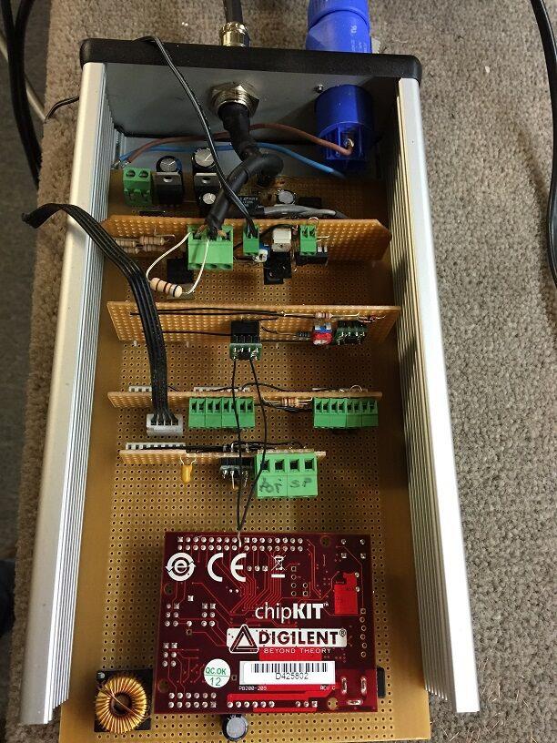
It looks like a pretty simple straight forward build but again I would suggest you get an oscilloscope so you can actually see what is going on when you are doing your adjustments.

As for the ironstone question - I have not tried to look for gold in solid ironstone so I dont know. I have not used my gear in anything other than mineralised ground so I dont know. The theory says it should work in both but not having tested it - I dont know.
 
SteelPat said:
Tim said:
In my opinion PIs' are highly over-rated. The biggest furphy being their ability to discriminate. It's all well and good to have something that punches deeper, but as soon as the ground conditions deteriorate it must be dumbed down. Indeed much of the Triangle is beyond the settings of any PI. Many production vlfs, including my GMT, also cannot inherently handle ironstone.

Sorry but I couldnt disagree with you more. PI's dont ever claim to discriminate as the current design theory does not lend itself for discrimination.

And PI's are not 'dumbed down' to compensate for mineralised ground. A Pi machine looks at the decay time of the signal. In mineralised ground that decay signal not only has the target decay signal but also the decay signal of the mineralised ground. What most PI machines do is try to determine that signal of the mineralised ground and subtract it from the combined signal, leaving only the target signal. Power is not reduced and generally there is no 'dumbing down'. If the ground is very severe, sometimes a different pulse train may be used where it can give the appearance of less power but its certainly not dumbing down.

As for Pi's in the GT - the evidence proves beyond any doubt that PI's out perform any other machine in the search for gold.

A good book to read and perhaps learn a bit of the theory behind it all is 'Inside the metal detector'. Its written by the guys who developed the Minipulse Plus. One was also a Whites engineer who now works for Texas.

Also you may need to get a cro if you really want to get the most out of the MPP kit. Timings can only be accurately done on a cro.
Age is showing there Pat with CRO... you gotta upgrade to the DRO :D

1444684999_14446848535920.jpg


If I had a surfpi built I'd give Tim the answer he's asking as straight up as his questions are.

Everyones text is informative and nothing wrong with oppinions here, but attitudes will have your comments ignored until you realise your just having a conversation with yourself. If you want to get a point across, cryptic text doesn't make it easier for anyone and its no fun playing any game by yourself.

I'm sure you all have some or proffessional experience, I can tell who knows what just from what they are saying, what parts they are talking about and how good the outcome of a device is. Wouldn't it be better to share our knowledge in a way that makes it useful for any member reading a thread like this, why not team up and make our own bloody detector..

I'm gonna confuse the hell out of you all. Supposibly there is some form of way to discriminate using an SDC2300. A club member is going to a training course to learn. Now is she getting ripped off or is there some form of discrimination possible..even if its not 'true' discrimination that mpst don't know of.. would a course really get you to pay for teaching nothing... its thrown me out just as much it will everyone here and I'm sure refusal will be the answer.

Constructive critisim and information text is more needed than arguments over discussions, at times they can't be prevented but can be maintained by those involved and coming to a truce even if sides are not equal. This is not directed to any one person

All I'm saying is try and keep it on topic with the building of surfpi or similar devices and share your knowledge, not yell it, please. I find the homebuilt detector threads very interesting and if anything we need more info on it all and anyones input to modify or change them helps.
Arrogance and ignorange just makes an infinite loop in discussions, posts ignored and left unanswerrd.

Its hard for someone like me who wants to learn, with arguing in between.

Ill also state..sometimes an 'argument' is needed for compromise or solid understanding but we keep it friendly and hate free :)
 
Marauder said:
OK so I'm just starting out on the metal detecting hobby, and having a reasonable amount of electronic skill, and not a lot of cash ATM, i'm thinking of building one of these DIY metal detectors, preferably a PI one.

Anyone built one or seen a reliable review of one? The Surf PI one looks good, but sounds more like a beach/coin hunter, where as i'm in the golden triangle looking for gold(coins/relic would be good to as i'm still a noob, would be good to find something)

Thanks
They work, they are a cheap good starters system to learn detecting but I would expect miracles with it. I constantly pick up old vlfs on ebay, gumtree and the rubbish...most just need a little clean and they still work.

If you like electronics and soldering get a diy kit..if not try and save for a cheap detector or search for one cheaply online. I started with a cnot soo cheap 400 dollar detector from minersden which didn't work.

If you can find an old coinmaster, goldmaster, compass or garret your laughing. I've bought old vlfs from $30-$120 for starter detectorsdetectorseaning for relics and coins...I wouldn't expect to find gold nuggets with a detector under $1200.

Hope it helps
 
Thanks for the info guys, I'm pretty set of the Surf PI 1.2, but can't get silverdogs website to work. Stack of SQL errors.

Electronicly speaking ground balance doesn't seem that hard to do with PI, assuming that it doesn't vary greatly over a given area, it should be easy enough to tune out, before the comparators. I'd also like to note here that if i'm talking out my arse feel free to point out.

My Plan is to buy two of the kits and set them up so that the electronics board is interchangeable to that i can mod one board and compare it with the original design. At the moment I'm thinking of adding ground balance(manual) and replacing the components with high precision pieces, to see if it makes a difference.

Also I'll just jump on the Discrimination on PI band wagon and say that i think it would be possible. As far as i understand the PI detector induces current in the target, which creates a magnetic field from the target, which in turn creates a current in the detector coil, which is observable whilst the pulse is inactive. Each type of target should create a different field, depending on the target composition, a different frequency probably, and the amplitude would be determined by size. With a micro controller you could compare these against known types(iron) and reject the signal(not relay the signal to the rest of the detector) ie discrimination. The only problem would being able to do the comparisons at speed. There are specific high speed comparators that are capable of this, but I'm sure its not easy to do in practice.
 
I'd probably stay away from buying things from silverdog until the sites fixed. I had no issues when I ordered the surfpi, took a couple of weeks but no problems at all which is always nice to know.

I think your idea of using two boards and comparing mods is a great idea and attempting more exact ICs / components. Some tweaking may be involved but you seem to not have an issue with that :)

My best advice I guess is make sure you buy the right one. SurfPI is popular but have a read and look at youtube to see if anything else is out there more suitable for your modding, in saying this, you may still stick with surfpi in the end anyway.

In the electronics world, if you have the know how, anythings possible. If only we all had the know how though...
 
I got mY DD commander second-hand for $90, but even if you have to spend $2oo it would be worth it so you have a good starting/referance point.

Thanks to all here for perservering. I don't want to alienate myself here-I realise I can come across a bit rough, so I will make an extra effort to be civil from here forward. :)
 
From what i've read the monoloop coils are better with the PI detectors, and the SDC2300 uses an 8" coil(very good reviews on this one). I'd also hazard a guess and say that the smaller coils generate less ground noise due to the lower volume of soil inside the magnetic field. Though I could be wrong(and frequently am)
 
Marauder said:
Thanks for the info guys, I'm pretty set of the Surf PI 1.2, but can't get silverdogs website to work. Stack of SQL errors.

Electronicly speaking ground balance doesn't seem that hard to do with PI, assuming that it doesn't vary greatly over a given area, it should be easy enough to tune out, before the comparators. I'd also like to note here that if i'm talking out my arse feel free to point out.

My Plan is to buy two of the kits and set them up so that the electronics board is interchangeable to that i can mod one board and compare it with the original design. At the moment I'm thinking of adding ground balance(manual) and replacing the components with high precision pieces, to see if it makes a difference.

Also I'll just jump on the Discrimination on PI band wagon and say that i think it would be possible. As far as i understand the PI detector induces current in the target, which creates a magnetic field from the target, which in turn creates a current in the detector coil, which is observable whilst the pulse is inactive. Each type of target should create a different field, depending on the target composition, a different frequency probably, and the amplitude would be determined by size. With a micro controller you could compare these against known types(iron) and reject the signal(not relay the signal to the rest of the detector) ie discrimination. The only problem would being able to do the comparisons at speed. There are specific high speed comparators that are capable of this, but I'm sure its not easy to do in practice.

Electronic ground balance isnt hard in theory - it's the electronics that will let you down. Basic idea is to get a sample with no target present - this is your ground base signal. You then subtract that from the mixed target response (this will contain target response and ground response). Then all that should be left is target. This is good in theory but in practice the ground signal will vary even moving a few cm away. Also you have EF to contend with. This is the signal that the earth itself creates. This too needs to be removed from mixed target response. Then there is EMI - another signal that needs to be removed.

I will post some more tech info on timings for basic GB/EF that I implemented on the MPP (via a ChipKIt Uno board that I wired to basic circuit) that will show you the basics of that. These timings work but the electronics let the thing down a little as they are a bit noisy and not fast enough.

As for the discrimination: With a PI you are not looking at the current created as such - what you are looking at is the decay time after the pulse has been turned off. Yes you are correct, the decay time does change for different materials and the basic idea of comparing it to known decay times will work - BUT - not with the way analogue receive circuits work. And unfortunately thats how most, if not all, kits are done (this goes for a most commercial pi machines too). There is a way around this which I have yet to implement. By using a ADC and taking 1uS (or less) samples straight after pulse turnoff (after any significant EMF if no snubber is in circuit) you can create a sample wave shape. After all EMF/EF and GB have been removed the resultant wave slope could be compared against known materials. This should work but as I said I have yet to implement it. I do have a ARM Cortex4 discovery board all ready for this project - just need time to do it.

Here is my modded MPP:
1444701561_mpp_mod.jpg


And this is a design of my own thats also controlled by a Chipkit Uno:
1444701595_ccpi.jpg


If you want more technical info ie timings/arduino code etc feel free to ask.
 
SteelPat said:
Marauder said:
Thanks for the info guys, I'm pretty set of the Surf PI 1.2, but can't get silverdogs website to work. Stack of SQL errors.

Electronicly speaking ground balance doesn't seem that hard to do with PI, assuming that it doesn't vary greatly over a given area, it should be easy enough to tune out, before the comparators. I'd also like to note here that if i'm talking out my arse feel free to point out.

My Plan is to buy two of the kits and set them up so that the electronics board is interchangeable to that i can mod one board and compare it with the original design. At the moment I'm thinking of adding ground balance(manual) and replacing the components with high precision pieces, to see if it makes a difference.

Also I'll just jump on the Discrimination on PI band wagon and say that i think it would be possible. As far as i understand the PI detector induces current in the target, which creates a magnetic field from the target, which in turn creates a current in the detector coil, which is observable whilst the pulse is inactive. Each type of target should create a different field, depending on the target composition, a different frequency probably, and the amplitude would be determined by size. With a micro controller you could compare these against known types(iron) and reject the signal(not relay the signal to the rest of the detector) ie discrimination. The only problem would being able to do the comparisons at speed. There are specific high speed comparators that are capable of this, but I'm sure its not easy to do in practice.

Electronic ground balance isnt hard in theory - it's the electronics that will let you down. Basic idea is to get a sample with no target present - this is your ground base signal. You then subtract that from the mixed target response (this will contain target response and ground response). Then all that should be left is target. This is good in theory but in practice the ground signal will vary even moving a few cm away. Also you have EF to contend with. This is the signal that the earth itself creates. This too needs to be removed from mixed target response. Then there is EMI - another signal that needs to be removed.

I will post some more tech info on timings for basic GB/EF that I implemented on the MPP (via a ChipKIt Uno board that I wired to basic circuit) that will show you the basics of that. These timings work but the electronics let the thing down a little as they are a bit noisy and not fast enough.

As for the discrimination: With a PI you are not looking at the current created as such - what you are looking at is the decay time after the pulse has been turned off. Yes you are correct, the decay time does change for different materials and the basic idea of comparing it to known decay times will work - BUT - not with the way analogue receive circuits work. And unfortunately thats how most, if not all, kits are done (this goes for a most commercial pi machines too). There is a way around this which I have yet to implement. By using a ADC and taking 1uS (or less) samples straight after pulse turnoff (after any significant EMF if no snubber is in circuit) you can create a sample wave shape. After all EMF/EF and GB have been removed the resultant wave slope could be compared against known materials. This should work but as I said I have yet to implement it. I do have a ARM Cortex4 discovery board all ready for this project - just need time to do it.

Here is my modded MPP:
https://www.prospectingaustralia.com/forum/img/member-images/4467/1444701561_mpp_mod.jpg

And this is a design of my own thats also controlled by a Chipkit Uno:
https://www.prospectingaustralia.com/forum/img/member-images/4467/1444701595_ccpi.jpg

If you want more technical info ie timings/arduino code etc feel free to ask.
Bloody hell Steelpat, you do my head in with all this technical nerdiness. :lol: :lol: Good stuff you're sharing there (i presume) mate. Well done :p
 
Thanks SteelPat, arduino code would be great as I've dabbled a bit in it. Would be interested to see what you've done re discrimination. While I've got a working knowledge of electronics, i'm primarily a process systems engineer, so the theory comes easy, but practical implementation is another thing.

I'll just have to email SilverDog and get him to fix his webpage!
 
#include <plib.h>
////********** INCLUDES FOR DISPLAY **********
//#include <CcPiOled.h>
//#include <Wprogram.h>
//#define OLED CcPiOledClass
//#define cbOledChar 8 //number of bytes in a glyph
//#define cbOledFontUser (32*cbOledChar) //number of bytes in user font table
////************************************************
//
////********** GLOBAL VARIABLES **********
//OLED oled;

//************************************************

#define SYS_FREQ (80000000)

void ShortDelay( // Short Delay
UINT32 DelayCount) // Delay Time (CoreTimer Ticks)
{
UINT32 StartTime; // Start Time
StartTime = ReadCoreTimer(); // Get CoreTimer value for StartTime
while ( (UINT32)(ReadCoreTimer() - StartTime) < DelayCount ) {
};
}

//Then define the clock frequencies:

#define CPU_CLOCK_HZ (80000000UL) // CPU Clock Speed in Hz
#define CPU_CT_HZ (CPU_CLOCK_HZ/2) // CPU CoreTimer in Hz
#define PERIPHERAL_CLOCK_HZ (40000000UL) // Peripheral Bus in Hz
#define US_TO_CT_TICKS (CPU_CT_HZ/1000000UL) // uS to CoreTimer Ticks
long start;
//volatile long counter = 0;
int TX_FREQ = 800; //IN uS = DEFAULT 1KHZ (1000uS)
int TX_WIDTH = 150; // TX DEFAULT
float MAIN_SAMPLE_DELAY= 10;
float MAIN_SAMPLE_WIDTH = 10;
int EF_SAMPLE_DELAY= 5;
int EF_SAMPLE_WIDTH = 60;
float GB_SAMPLE_WIDTH_1 = 150;
float GB_SAMPLE_WIDTH_2 = 140;
float GB_DELAY = 35;
int TX_PERIOD = TX_FREQ * 1.25;//

//int RX_SIG_IN = A0; // set the sample pin
int GB_DELAY_ADJ = A1; // GB_DELAY adjust pin
int EF_WIDTH_ADJ = A2; // EF_SAMPLE_WIDTH ADJUST PIN

void setup()
{
// oled.begin();
pinMode(34, OUTPUT);//RD5 TX_PULSE
pinMode(36, OUTPUT);//RD6 RX_GATE_1
pinMode(37, OUTPUT);//RD6 RX_GATE_2

OpenTimer1(T1_ON | T1_PS_1_64 | T1_SOURCE_INT, TX_PERIOD);
ConfigIntTimer1(T1_INT_ON | T1_INT_PRIOR_1);
INTEnableSystemMultiVectoredInt();
LATDSET = (1<<5); // Set pin 34 high (TX_PULSE)so we can use inverted pulse output
LATDCLR = (1<<6); // Set pin 36 LOW
LATDCLR = (1<<7); // Set pin 36 LOW
}

void loop()
{

}

extern "C"
{
void __ISR(_TIMER_1_VECTOR,ipl1) pwmOn(void)
{
mT1ClearIntFlag(); // Clear interrupt flag

//*********** BEGIN GET POT VALUES ************************
float GB_POT_VALUE;
GB_POT_VALUE = analogRead(GB_DELAY_ADJ); // get pot value
GB_DELAY = map (GB_POT_VALUE, 1, 1024, 5, 50); // VALUES 5us TO 50us
float EF_POT_VALUE;
EF_POT_VALUE = analogRead(EF_WIDTH_ADJ); // get pot value
EF_SAMPLE_WIDTH = map (EF_POT_VALUE, 1, 1024, 10, 100); //VALUES 10us TO 200us
//*********** END GET POT VALUES **************************

//*********** start EF sample ***************************** NOTE: THIS IS SET TO PORT D6 - MAY HAVE TO SET TO D7
LATDSET = (1<<6); // SET PIN36 or PORT D6 high RX_GATE
ShortDelay(EF_SAMPLE_WIDTH * US_TO_CT_TICKS ); // WAIT EF_SAMPLE_WIDTH THEN TURN OFF GATE
LATDCLR = (1<<6); // SET PIN36 or PORT D6 low RX_GATE
ShortDelay(EF_SAMPLE_DELAY * US_TO_CT_TICKS ); // WAIT EF_SAMPLE_DELAY THEN TURN ON TX GATE
//*********** end EF sample *******************************

//*********** BEGIN TX PULSE ******************************
LATDCLR = (1<<5); // set PIN34 or PORT D5 Low
ShortDelay( TX_WIDTH * US_TO_CT_TICKS ); // SET TX_WIDTH
LATDSET = (1<<5);// Set PIN34 or PORT D5 High

// *********** END TX PULSE *******************************

//*********** begin main sample ***************************
ShortDelay(MAIN_SAMPLE_DELAY * US_TO_CT_TICKS ); // WAIT DELAY THEN TURN ON GATE
LATDSET = (1<<6); // SET PIN36 or PORT D6 high MAIN SAMPLE
ShortDelay(MAIN_SAMPLE_WIDTH * US_TO_CT_TICKS ); // WAIT THEN TURN OFF GATE
LATDCLR = (1<<6); // SET PIN36 or PORT D6 low RX_GATE
//*********** end main sample ***************************

//*********** start GB 1 sample ***************************
ShortDelay(GB_DELAY * US_TO_CT_TICKS ); // WAIT GB_DELAY THEN TURN ON GATE
LATDSET = (1<<7); // SET PIN36 or PORT D7 high
ShortDelay(GB_SAMPLE_WIDTH_1 * US_TO_CT_TICKS ); // WAIT GB_WIDTH THEN TURN OFF GATE
LATDCLR = (1<<7); // SET PIN36 or PORT D7 low
//*********** end GB 1 sample ***************************

//*********** start GB 2 sample ***************************
ShortDelay(GB_DELAY * US_TO_CT_TICKS ); // WAIT GB_DELAY THEN TURN ON GATE
LATDSET = (1<<6); // SET PIN36 or PORT D7 high
ShortDelay(GB_SAMPLE_WIDTH_2 * US_TO_CT_TICKS ); // WAIT GB_WIDTH THEN TURN OFF GATE
LATDCLR = (1<<6); // SET PIN36 or PORT D7 low
//*********** end GB 2 sample ***************************

}
}

Its not pure Arduino as the Chipkit is slightly different but I have commented most of it. I havent implemented discrimination yet as thats for the ARM board.
 
That version has a few bits in it for the display but it uses 2 GB samples at different delays. This is only one of a few different timings I was experimenting with. I ended up loading all the timings and using a rotary encoder to select each one.
 
I hadn't had the chance to play with Ardiuno board yet..but I tell ya what...that looks much neater than having to deal with PICs and its problems with setting up chips / definitions...analogread..digital read..its soo much simpler..they even have a digital / analogue converters imbeeded as well don't they. Is this only controlling a lcd display or it does output an audio as well?

Only three sorts of people understand binary. Those who do and those who don't..

I'm going through it slowly, but with no ardiuno experience I'm useless to understand this and knowing definitions

Keep it up guys.. very interesting..
 
I havent programmed a pic chip for many years. All the development boards have so many extras and are easier and faster to program.

When I need a basic board, I prefer the ChipKitUno board over the standard Arduino boards because it has a faster clock speed and more I/O's. It does have some analog inputs but the resolution is pretty low. You can get plenty of add-on shields that give you things like audio, relays etc.

The Arduino boards are cheap and there are heaps of sample sketches (programs) to learn with. The good thing is if you make a mistake, you just re-program it and try again.

I got a Arm Cortex4 discovery board a while ago that has a higher resolution a/d converter, built in audio as well as a few other bits. This is what I was going to use for my next project but thats not Arduino. I will use either Keil IDE or Visual Studio and it's a lot more involved when it comes to programming.
 
SteelPat said:
I havent programmed a pic chip for many years. All the development boards have so many extras and are easier and faster to program.

When I need a basic board, I prefer the ChipKitUno board over the standard Arduino boards because it has a faster clock speed and more I/O's. It does have some analog inputs but the resolution is pretty low. You can get plenty of add-on shields that give you things like audio, relays etc.

The Arduino boards are cheap and there are heaps of sample sketches (programs) to learn with. The good thing is if you make a mistake, you just re-program it and try again.

I got a Arm Cortex4 discovery board a while ago that has a higher resolution a/d converter, built in audio as well as a few other bits. This is what I was going to use for my next project but thats not Arduino. I will use either Keil IDE or Visual Studio and it's a lot more involved when it comes to programming.
Cheers for that info mate

As long as your only having to write in a C language and not another one you gotta learn like poxy Python you'll be right hehe
I never got far in it all..you guys are well ahead of what I learnt back then. All my electronics is packed up and away for when the interest needs to come into play again :)

I was more interested in how components are made for survival purposes ;) :) and most components can be made from very simple McGuyva fiddlings
 

Latest posts

Top