Motorhome Solar Power System Issue

Prospecting Australia

Help Support Prospecting Australia:

This site may earn a commission from merchant affiliate links, including eBay, Amazon, and others.
Thanks Condor & Jon,

Thought as much! maybe we should get a boat? I guess $100 will buy just under 1/3 of one new battery :( .

We bought the batteries in Dec 2013, started dropping power about Jan this year.

We are going to buy a new charger, should we go for a 35V or 50V. I was told buy the Battery guy (Bob), that the 50V is a little overkill? And eventually 3 new batteries. Should we still run 3 x 130ah, I think you worked out it was enough for the panels?

Will probably chuck the third battery, maybe run the other two till they die completely,can't hurt them any further and they are still running most of our needs during the day while the sun shines.(just not my microwave 8.( , I will live without it I guess.)

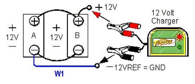
Bob explained how we should have had the batteries hooked up for charging, (if he's right?) batteries in parallel, positive attached to first battery, negative to last battery then both to battery charger & MPPT/solar panels? Bill didn't have them hooked up that way he had them in parallel but with positive and negative on the first battery. Bob seems to think that's is why they tested progressively worse, as in the first battery would have been getting most of the charge and the 3rd one getting the least? Does this theory ring true with you?

Will look at a better monitoring system to tell us the ins and outs. I guess the cycling too deep would probably be the inverter at fault? Even if it is only ran a short time a couple of times a day , the batteries would not be getting a chance to recharge enough to recover? Is this correct? I think I'm grasping it all. ;)
When Bill is back next week I will have get him to read the posts, so he can take on-board all the information and suggestions kindly offered.
Looks like we will be starting from scratch to set up our system? Have learnt a very expensive lesson, I thought we had researched this solar thing pretty well before we started :8 , but have realised obviously not enough.
 
I'll do a simple circuit diag for you Fluffy.

I don't understand the 30V / 50V (in the 4th line) I'm assuming a typo and should read 30A / 50A. In other words Amps not Volts.

He's wrong in one thing, my 1st van had 2 x 100 AH AGMs charged from a 30A charger. Your bank is almost double that so it is logical to increase the charger size so 50A is not overkill. Particularly in that you are using significant power when using the inverter, which needs replacing before you use the inverter again, otherwise the battery will eventually go flat.

Also, consider that if you run a 50A charger set to 50 A and your panels are charging at the same time, you are putting in a significantly high charge. Your 2 x 250A panels can put in as much as 30A as well, that is "overkill". My advice is use one or the other, not both at the same time. This is why I installed "soft make" circuit breakers, the scenario being;

When in a caravan park on mains power, I use the 15A charger to keep the batteries charged, I don't want to be putting in a another 15A from the panels at the same time for the size battery I have. However I also have the original 30A transformer/charger that came with the van (which is not suitable for charging an AGM). So once my battery is full, I have switches installed, that do this - Van park or home - The Transformer supplies all 12V to the van and is ON, the 15A charger is turned ON to maintain battery, the solar panels are OFF and the battery is OFF. Free Camp - Battery and Panels both ON, Charger and transformer both OFF. Plus at any point or in any configuration, I can monitor the battery on my smart phone.

I'll post my set up diagram so you can see what I do, keep in mind it is not exactly how I would do it from scratch, it's been modified to do what I want and maintain warranty on original equipment.
 
The circles near the top of the diag noted C & M are external cig socket and merit socket.
I added them and; solar panels with circuit brkr, solar controller, 15A AGM charger, fuse block, SW3, USB power sockets, BCDC1220, 12V GPO for inverter, diesel heater and the BMPRO.

1460610650_van_electrics.jpg


I can draw up something to explain banked battery in parallel, but I'll see if there is something on the web first.
 
This is an example only that I found showing what your battery bloke said

1460610895_series9.jpg


adding a 3rd battery or more is the same principle. Also, you would use the same logic for all charging and outputs.
 
Another consideration of banking large battery output is the interconnecting cable size needing to be matched to the largest draw, which in your case is the inverter. The cable size, inverter to battery likewise. Then all other cables are of the size relevant to the current draw or charge of the item, keeping in mind length of cable v current = voltage drop (figuratively speaking).
 
Fluffy,

Bob is effectively saying that the cabling between the batteries has a real resistance. If you consider your three batteries as one you should have negligible resistance between batteries just like a single 390A battery. With the way you connected your charger Bob is saying the furthest battery received less charge (although probably marginally) by this cable resistance. This would only be true if your inter battery cabling is too small for the charge current, or the current drain, and also really only for higher currents in the bulk and initial absorption ranges. So if you maintained your connections and your battery interconnect cables are large (starter cable size) and provide negligible resistance then there shouldn't be an issue. But only you can say whether this could be a problem with your setup.

If there is a resistance in the cables then to get around this somewhat you could position the charger cable as the diagram for the two batteries that condor22 sourced as an example of Bobs description. But this connection assumes that the loss for the inter battery positive cable is equal to the negative. If the positive cable has a loss due to a dirty connection then the battery closest to the positive charger will be charged quicker than the one furthest away so maintenance is a major requirement.

I would ensure the inter battery cabling creates negligible resistance for your operating and charging conditions and are of equal length. Then maintain the connections to ensure there is negligible resistance. There is no harm in hooking up your accessories and charger as Bob's suggestion, if there is an equal loss over the positive and negative cables then it should compensate for that.

Now I am really truly off for a dig (had to turn around nearly arrived :( ).

Jon
 
One thing we learned when first venturing out in our new van in 2008, when parked up free camping there was never a problem keeping the two 110AH AGM's fully charged. Usually solar was enough but occasionally a generator/battery charger boost connected as per Condors #64 post.
Bought a couple of wireless fridge monitors, one for the van and the other for the Engels on the ute so we could keep an eye on our month supply of vegies and frozen food from the cab of the vehicle.
The van has a auto changeover device which selects which ever charging device is connected. eg: 12V input from vehicle, 240V from mains or generator and lastly solar.
We usually travel 1000km's to our goldfields and along the way the van fridge is running on 12V, (gas when parked up) and batteries being topped up by vehicle alternator.
During first trip soon realised that the wiring supplied by Caravan Business from vehicle to van batteries was not enough to keep up the charge (Too much voltage drop). The fridge temperature was on a slow upwards slide hours into the trip.
When we got home I fitted welding sized cable from vehicle auxiliary battery to the van batteries with an Anderson plug between vehicle and van. Also fitted a 100amp fuse either end one adjacent to van batteries the other at the vehicle auxiliary.
To this day have never had a problem with maintaining battery levels in the van and keeping the fridges at or around 2C, freezers -15C while travelling.

So Fluffy, with my limited technical knowledge your early battery failure is undoubtedly due to what Condor quoted: The 2 common reasons for this happening if they are not that old are;

Improper charging - know what you put in

Cycling too deep, too often - Know what you take out


Cheers
Peter
 
Nightjar,

Agreed and exactly my point. The main reasons I chose not to boost the wiring were;

It would have been a "pig" to route the wiring in the van and also the vehicle, 6mm is sufficient to get power to the van battery area albeit with too much voltage drop.
I chose the Redarc BCDC1220 for 3 reasons as stated; 1. They run on as low as 9V, so my 11.9V or so was more than enough using existing wiring and handle the input current 2. Being right next to the van battery there is no voltage drop from charger to battery. 3. They charge at the correct voltage and amperage to properly charge, whereas, even in a perfect world of getting 13.8V back there, it's still not enough to get the best out of an AGM.

The down side is @ $310 (at the time) it's the more expensive option initially, but it will pay for itself over the life of the van and battery and will handle a bigger battery, if at some future time I get a compressor fridge in the van and increase the battery capacity.
 
Hello all, I have read all the posts and suggestions, thankyou to everyone for the contributions, I now have some serious thinking to do again.

I obviously need new batteries, I was thinking of going for two of these:

http://www.ebay.com.au/itm/HVT225D-...OLAR-MARINE-/321657632449?hash=item4ae449f6c1

I still need the cranking capacity as my generator (7KVA Onan onboard generator) is started from the battery bank, plus there is the 150ah draw for the inverter/microwave occasionally.

I have been rethinking the battery management and was wondering what anyone's thoughts of this controller is?

http://www.redarc.com.au/products/product/themanager30/

It seems to take care of all my needs for keeping the batteries in good condition, I think?

Does anybody know of any similar products that would manage the system, and perhaps a little cheaper? I can get this management system for $1495.
Obviously the price is getting up there, but I don't want to kill any more batteries and go backwards.

I have included diagram of how our system was originally, which we obviously will change.https://www.prospectingaustralia.com/forum/doc/member-docs/7277/1460944126_solar_setup_as_it_was.pdf

thanks Bill & Karen :(
 
Fluffy

1. Using 2 x 240AH increases your bank to 480AH from 390, the solar input and suggested replacement charger will still handle the increase, but will take longer to charge when if you draw say 50%. As I said 25-50% cycling is maximum for battery life and this will give you more usable juice. However there are only so many hours of daylight for solar and in a day for 240VAC charging. It will all depend on how much you use.

2. The Redarc BMS max range of 520W is getting close to the 500W output of your panels. I suggest you drop Redarc Techos an email and tell them what panels you have and the suggested battery type and total AH and ask for some guidance from them.
 
Also bear in mind the Redarc BMS has a 50A limit which is no where near enough to monitor the Inverter directly.
 
Hello All,

Well have been doing my head in with research etc., and with a bit of help from my electrician son we have come up with another option, this time I'm pretty sure it will be okay. The Redarc 1240 and the BMS1230S2 will only handle an input from the solar panels of 32V UoC according to their specifications and our panels put in 37.9 so we had to scrap that idea.

Looking at upgrading our 240V charger to the epower 40 amp charger or the Projecta IC5000 (I am fairly certain that I wouldnt need to go as big as the epower 60 amp charger.)

I have decided I don't have the room for the 240 AH batteries so will go for either 3 or 4 x 130 ah agm batteries (I can split them up into two different cupboards).

We are looking at purchasing the 30 amp Enerdrive Dc2Dc epower charger and the EPro battery monitor in replacement of our present MPPT controller to utilise the alternator of the vehicle.
We are just a little concerned with dropping down from a 40 amp controller to a 30 amp controller.

http://www.enerdrive.com.au/product/dc-to-dc-battery-charger/

http://www.enerdrive.com.au/product/epro-battery-monitor)

http://www.enerdrive.com.au/product/epower-12v-40a-battery-charger/

http://www.enerdrive.com.au/product/epower-12v-60a-battery-charger/


Would you be able to give some advice as to whether these units would suit our solar panels? Have also emailed Enerdrive to see what they have to say about the components as well. I have attached a photo of the solar panel specification.
1462785414_solar_panel_specs_edited.jpg


Once again all your advice/comments are very much appreciate. (My metal detector purchase has been put on hold till I recoup the kitty 8.( )

Kind Regards,

Bill & Karen
 
Bill, I wasn't aware earlier re the DC panel output volts. Herein lies the biggest issue, they are well above most controller voltages, however the total output is nominally only 16.24 A. Which means that when going through a controller down to 13-14 V for a 12 volt system most of the 250 W will be absorbed by the controller in stepping down. I would expect your solar input to be about 14+ amps max, which equates to less than 200W. You won't get half of the 250 x 2 panels = 500W when on a house system.

I get the same from my 2 x 100W panels that run at about 19VDC before the controller.

So in my opinion house panels are not the best option.

Your panels W - A x V or W = 8.14 x 31.06 = 252.8 W

however you won't get more than 8.14 A at output and the voltage is about 14.4 at boost so the W = 8.14 x 14.4 = 117W.....

I kind of think your whole problem has been that you have never got close to half of the 500W you thought you had....... check this with you sources and let me know if I'm correct.

I'm in the goldfields for 6 weeks, so not online often
Mike
 
Have a look at GSL electronic products. Designed and made in Australia,
I have the MPPT 30-1 in my camper trailer with a 240 watt grid connect domestic type panel (same as yours) and 2 x 10⁵ah batteries. Best I have seen it charging was 13 amps. http://www.gsl.com.au These products are designed for the cheaper grid connect panels.
 
These solar controllers use inverter type technology and are typically >85% efficiency. Using this figure, a 250W solar panel would deliver 212W at peak power which at 14.4V is around 14.7A each panel. Given that the sun will rarely be perpendicular, you would expect a lesser figure, so woolly's observation of above looks spot-on.
 
Today was very very overcast in the VIC goldfields, I checked last nights usage at 15% or 18AH this morning (including the diesel heater), turned my panels on at 0900 and returned to the van 4 hours later, the battery was at 100%. So very impressed.

Have used more tonight so will leave panels on as they start charging at dawn and leave all day.
 
condor22, thanks for the info. Just what you expect from an installation that is done correctly.

A caution for buying wire.
My local auto shop tried to sell me 6 mm round when I asked for 6mm square. I was advised by them that the round is what they sold to 'everyone' for this application. The round has a cross sectional area of about 4.5mm which is substantially less than specified. It won't carry the required current.
The wire was for electric van brakes, a critical application. Any wonder products don't work as advertised.
 
bazxa said:
condor22, thanks for the info. Just what you expect from an installation that is done correctly.

A caution for buying wire.
My local auto shop tried to sell me 6 mm round when I asked for 6mm square. I was advised by them that the round is what they sold to 'everyone' for this application. The round has a cross sectional area of about 4.5mm which is substantially less than specified. It won't carry the required current.
The wire was for electric van brakes, a critical application. Any wonder products don't work as advertised.

Too early in the morning, can you explain 6mm round as apposed to 6mm square?
 

Latest posts

Top