A question for the Techxperts

Prospecting Australia

Help Support Prospecting Australia:

This site may earn a commission from merchant affiliate links, including eBay, Amazon, and others.

Moneybox

Philip & Sandra Box
Joined
Oct 10, 2014
Messages
4,202
Reaction score
17,751
Location
Cue, WA
I have a 24v electrical system in my vehicle. When I purchased my two 3.5 cfm compressors I could only get them in 12v. Each compressor draws a maximum 40A.

1488163593_compressor_wiring.jpg


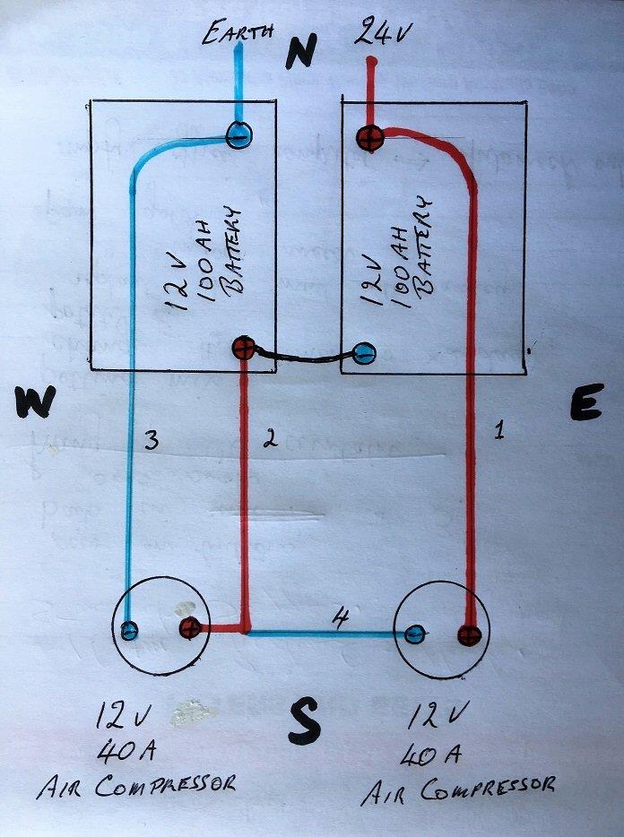
To simplify the diagram it does not show the related switches and relays. I've marked the illustration N,S,E and W.

Q1, What is the direction of current flow in each cable 1, 2, 3 and 4
Q2, When the compressors are drawing their maximum draw, what is the current draw on each cable 1, 2, 3 and 4
Q3, If one cable differs from the others explain why
 
Wire number 4.
Run it too the negative on the right hand battery.
Are the compressors insulated. ?
IE: No metal to chassis earth.
If they are, There will or can be some interesting results.
 
Tathradj said:
Wire number 4.
Run it too the negative on the right hand battery.
Are the compressors insulated. ?
IE: No metal to chassis earth.
If they are, There will or can be some interesting results.
I wrote a big long thing and deleted it all, some things are missing from the diagram :rolleyes: :lol: :lol:
If the 12v system is isolated from the 24v what did you use?
As Tath said , 4 wire to batt, if it's isolated, guess on a current draw 22A +- 4A normal load
Wire gauge and length effects current draw due to resistance
http://www.engineeringtoolbox.com/amps-wire-gauge-d_730.html
Edit should have added :rolleyes: is the right compressor not running
 
Are the compressors run at the same time? If not you'd wind up with a charge imbalance over the batteries. If run at the same time I question the purpose of wire 2. If the compressors use exactly the same current then wire 2 would be zero current otherwise a charge imbalance would occur with a current equal to the compressor current imbalance measurable on wire 2. If the W compressor uses more current then the current imbalance would be headed S on wire 2 discharging the W battery at a greater rate than the E battery. i.e. if the W compressor uses 1 amp more than the E compressor then you'd see this 1amp on wire 2.

If it were me I'd ditch wire 2 and run the compressors in series with one relay and switch. Complicated circuits can have complicated results as Tath pointed out.
Jon
 
1. Ok we don't have to get too technical. We're using heavy cable so voltage drop over the length of the cable in insignificant.
2. Yes the compressor internals are fully insulated. Return earth is needed.
3. Only three cables have been run to the compressors to limit the amount of wiring in the harness. The compressors are mounted side by side so cable 4 is quite short.
 
I'd be concerned that the current drawn by the compressors was not clean DC (i.e.: pulsed DC - commutators etc), and will vary depending on the load on each, requiring preferably 4 wires (3 minimum) for reliable operation.
 
Both compressors run at the same time. They draw their power from different batteries to help keep the batteries balanced. Each compressor has a separate circuit breaker and relay activated by ignition and limited by a 160 psi cut-off switch on the 20L holding tank. They restart when the pressure drops to 120 psi.

Wire two is included to ensure that each compressor is being fed 12v. If one compressor were to fail for any reason the second compressor will continue to operate independently.
 
It can be argued that Positive flows to Negative but it actually
flows the other way. (No Fighting. LOL )
Each motor is defined as a load,
ie:resistance.
Each positive will load to 20 amps peak.
The center negative conductor will load to 40.
Then take into consideration each battery's condition.
That is taking into consideration that all leads are the exact same length.
May I ask how long a run is it MoneyBox. ?
Seriously thick stuff is warranted.
No offense, I would use 4 conductors.
.
Also, I think you may find that the first motor that the
centre lead is connected to, Will rob the second one.
Power or electricity as we call it is lazy stuff. It will find the
easiest path to run. :)

1488170616_wiring_diagram.jpg
 
BW has a good point as the load changes between the compressors could affect each other. Ideally you'd have 24v redundant compressors but you have to work with what you got and there will be a current imbalance.
Jon
 
In it's present configuration wires 1,3 and 4 are 6mm
Wire 2 is 8mm

Wires 1,2 and 3 are approximately 2m long.
Wire 4 is about 0.4m long

The setup has been in operation for about 12 months and works well.
 
Moneybox said:
In it's present configuration wires 1,3 and 4 are 6mm
Wire 2 is 8mm

Wires 1,2 and 3 are approximately 2m long.
Wire 4 is about 0.4m long

The setup has been in operation for about 12 months and works well.
Here I'm thinking there 3 to 4 meters and cables not wires, :lol: :lol: :p Match wire 2 size with wire 4 to batt- E 8mm
If it works fine why change it :eek: It's tried and tested or are the compressors running different to each other?
 
I've been happy with the performance of the compressors. I've had an air leak causing the compressors to fill the tank every day at start up and we could hear them come in at times as we travel. This time I managed to track down the air leak on a pneumatic ram on the side step. I never looked there before.

I'm doing a three year refit and tidying up a few things. I confused myself when I tried to work out how I had wired the compressors so I had to put it on paper. Then I thought to myself "What type of current flow do I have on wire 2. Is it + to -, - to+, that poor little wire must be confused :) ". I should have had it dashed red-blue-red-blue.

If the 'W' compressor is running then the current runs one direction but if the 'E' is running then the current is reversed in wire 2. What goes on when they are both running as they always do?

It's really not important but I thought I should put it out there..... :D
 
Net zero current on wire 2 if both compressors use 40 amps. Then 40 amps on all other wires including the unlabeled inter battery cable. If there is a current imbalance between the compressors this will show on wire 2.
Jon
 
Circuit is broken on one leg of the positive supply so
with just either one running, You have an open circuit.
What would worry me is what the result would be if something
went wrong.
The cable that would cop it is number 2.
It would turn into a light bulb filament fusing every thing else around it.
I would say that your batteries are very hefty.
You would be able to weld off them. :) :)
Oh, Having two separate circuits give you redundancy and safety.
 
I didn't quite give you the whole story. These are the Isuzu start batteries. I didn't draw the compressor power from the 4x120 AH deep cycle batteries because it gets even more complicated. The compressors only run with the ignition on and therefore the alternator is charging. If I took the power from the 24v deep cycle batteries then I would be using power that has to be delivered from the start batteries via a secondary charger.

Yes Tathradj I'm sure I have sufficient power to run a stick welder. I should wack the electrode holder on and see the outcome. It would be a handy addition to the toolkit.
 
limpalot said:
I would have run wire 4 to the neg on that battery, if that motor shorts you will have 24v in the other motor.

I have 50A self-resetting circuit breakers in wire 1 and 3. I believe wire 2 prevents 24v feed to either compressor.
 
LOL,
Remove them from the vehicle and use a 1.5 foot of number 8
bull wire between them as a choke.
Actually it is 36 volts to do it.
I seen a bloke welding like this with a helmet made out of a weetbix
box with a welding glass stuck in it.
Saved room he reckoned. :cool:
Till it caught fire. :lol: :lol:
 
Moneybox said:
I didn't quite give you the whole story. These are the Isuzu start batteries. I didn't draw the compressor power from the 4x120 AH deep cycle batteries because it gets even more complicated. The compressors only run with the ignition on and therefore the alternator is charging. If I took the power from the 24v deep cycle batteries then I would be using power that has to be delivered from the start batteries via a secondary charger.

Yes Tathradj I'm sure I have sufficient power to run a stick welder. I should wack the electrode holder on and see the outcome. It would be a handy addition to the toolkit.
My ex boss has one on his bash car, I'd get one if I were you on the beast you run :lol: :lol:
Its an alternator with no reg box so AC arc welder at 3000 rpm
He had a locally made one can't remember who did them here but the guy made one from I think it was a 110A alternator with the reg removed and modded and set up with electrode connectors :cool: very cool welded many a vehicle back together
If you ever see Variety Bash car 0 ,huge white Tank Fairlane come through town ask Jack for a look under the bonnet ;)
Not the one he had but there is a few company's producing :)
http://www.zena.net/
 

Latest posts

Top