Electronics guru assistance required

Prospecting Australia

Help Support Prospecting Australia:

This site may earn a commission from merchant affiliate links, including eBay, Amazon, and others.
Joined
Jun 4, 2014
Messages
4,653
Reaction score
9,516
Location
Newcastle, NSW
Good morning all
My soundbar shat itself mid race last night
Its out of warranty , im not a real eleco (restricted licence) so not a complete twit
Got 240 in but no output
Primary fuse is ok
There is mention in the user manual (cant find a service manual) of protection circuit ... take unit to your Yamaha guy...
Well thats only gonna happen if I cant fix or @#$& it myself :playful:
1637444937_e579f84e-970f-4481-adc4-705c50f0d4e4.jpg

I havent got any lights at all... at least one capacitor had charge though... THAT WOKE ME UP! :8
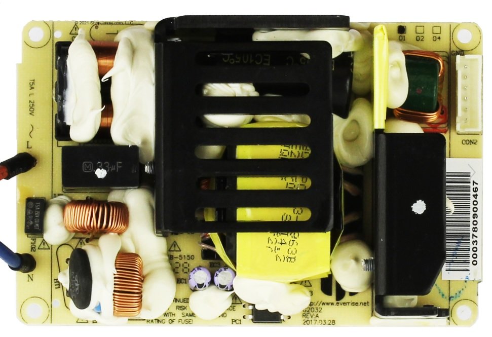
So ... heres a pic of the power module
The only thing not covered in goop appears to be marked PC1 (?protection circuit ?)
1637444177_dc4d26f2-9464-49b6-a6dd-ee1833af8ac9.jpg

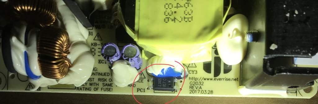
Ive put my meter across it and got nothing (ohms) but not sure of value should be looking for either (or voltage for that matter but assume 12v from transformer)
Can you please identify/confirm this piece is the likely culprit
Cheers
 
Just a long shot Sandta. I just entered the web address that is on the circuit board in your photo and it takes me to the company website in China (The site is in English). Would it be worth trying to email them with the same photo and questions? They have a contact link.

As for being any help to you, my experience and knowledge with such things goes something like this- 1. Poke the little copper coil thingies buried in dried custard stuff with a screw driver, because, well,,, they just don't look right.

2. Stick the screwdriver in between the two purple things and see if that piece of custard comes off.

3. Get a zap off of the little purple things and curse, throwing the whole effing thing across the room.

4. Walk over and pick it up, wishing I hadn't done that, only to then wonder what is now missing from the vacant spot on the circuit board.

5. Crawl around on the floor on my hands and knees until I find the little black square thingy with the small writing on it and the broken legs, and decide that it is so small and insignificant that it probably didn't do anything anyway.

6. Curse China, then go to the shop and buy a new soundbar.
 
Well spotted Simmo :Y: Exact same numbers, Fresher looking custard, and even has a slotted bump guard on the newer version to help protect the little black square thingies with the fragile legs, when you hurl the the whole thing across the room :Y: :perfect:
 
Sandta
The black thingy in between the two chokes label HT1 looks like a varistor which is used to protect over-voltage it can be checked by using a multimeter. This will on the primary side of the circuit eg 240v. You will need to de-solder 1 leg to check it. Make sure there is no power on when checking.
cheers db
 
Deepseeker said:
Just a long shot Sandta. I just entered the web address that is on the circuit board in your photo and it takes me to the company website in China (The site is in English). Would it be worth trying to email them with the same photo and questions? They have a contact link.

As for being any help to you, my experience and knowledge with such things goes something like this- 1. Poke the little copper coil thingies buried in dried custard stuff with a screw driver, because, well,,, they just don't look right.

2. Stick the screwdriver in between the two purple things and see if that piece of custard comes off.

3. Get a zap off of the little purple things and curse, throwing the whole effing thing across the room.

4. Walk over and pick it up, wishing I hadn't done that, only to then wonder what is now missing from the vacant spot on the circuit board.

5. Crawl around on the floor on my hands and knees until I find the little black square thingy with the small writing on it and the broken legs, and decide that it is so small and insignificant that it probably didn't do anything anyway.

6. Curse China, then go to the shop and buy a new soundbar.

:lol:
I know that scenario oh too well ;)
 
deepblue said:
Sandta
The black thingy in between the two chokes label HT1 looks like a varistor which is used to protect over-voltage it can be checked by using a multimeter. This will on the primary side of the circuit eg 240v. You will need to de-solder 1 leg to check it. Make sure there is no power on when checking.
cheers db

Thanks mate
Ye i did check that already
 
to me, it looks like its a SMPS power supply, not transformer type because there is no transfo I can see AND there are 2ea ICs on the PCB... SMPS are dirt cheap!?!
The varistor is only there to limit current surge at power on, so you dont blow the fuse turning it on
I bet my bottom dollar you have a blown IC... bin the thing ya cheap skate

Meanwell make great SMPS which I use to power a Class A stereo amplifier

good luck!
 
Not trying to start an arugument, but top left of Simmo's pic looks like a Transformer to me, I see a few chokes too, whats under that heat sink in the middle of the pic ?

I will be happy to be set straight, I can always learn a lesson.
.

I don't think it he is being cheap, but looking to learn and fix if possible.
This is how I teach my girls. Broken gear not worth repairing is great for them to pull apart and study.

Kato was teaching M2 last night after C broke a 10" tablet :8 , at least it works as a teaching aid now, the girls are in awe that there is so little inside.
Most of my PC's are 'coverless' which would be a cooling problem if they did any real work, the kids often ask me questions about what is what inside them.

M1 is building a bridge for STEM, I demonstrated the Leonardo "da Vinci bridge" principles using an archery Bow, strung and unstrung.
They have 300 toothpicks and 1m of string.

;)
 
Just taking a guess from the photos:

1637547555_board.jpg


HT1 looks like an NTC thermistor placed in series to limit inrush current on power up.
The blue component right next to it (under the foam) is probably a varistor placed across the mains input.

The black IC Sandta circled is an optocoupler used to provide isolated feedback through R13 to PWM controller chip U1 to control switching and regulate voltage output.

The transformer is in the middle of the pcb under the heatsink, where the switching transistor might be mounted.

I think you should be able to work it out Sandta. I find it satisfying to get something working again for a few dollars instead of throwing it in the bin.

Wouldn't recommend the average hobbyist poke around an SMPS board though, especially with the cheap multimeters that most people have.
 
deepblue said:
BigL you might be a little confused in your idea of the varistor.
Varistors don't limit current they are purely a voltage dependent device and are used for protection against voltage spikes.
https://en.wikipedia.org/wiki/Varis... is only used for non-ohmic varying resistors.

https://au.element14.com/ge-sensing-thermometrics/cl-60/ntc-inrush-current-limiter-10/dp/1653469

read the Product Overview section in above link.

I use a CL-60 Themistor in my Class A amp I built, specifically to stop blowing the fuse at power up

Had a closer look at the pic, yes it is a transformer PSU with CLC filtering
 
Little flat black thingy looks like an NPN Phototransistor Output Optocoupler ,Might be the culprit?....But don't have a clue actually. :D
 
Just use a FBH and if that don't fix it, just get a new one..... :p
 

Latest posts

Top