Chestcold F 40 3 way fridge . 12 volt thermostat .

Prospecting Australia

Help Support Prospecting Australia:

This site may earn a commission from merchant affiliate links, including eBay, Amazon, and others.
Joined
Oct 3, 2019
Messages
1,120
Reaction score
1,000
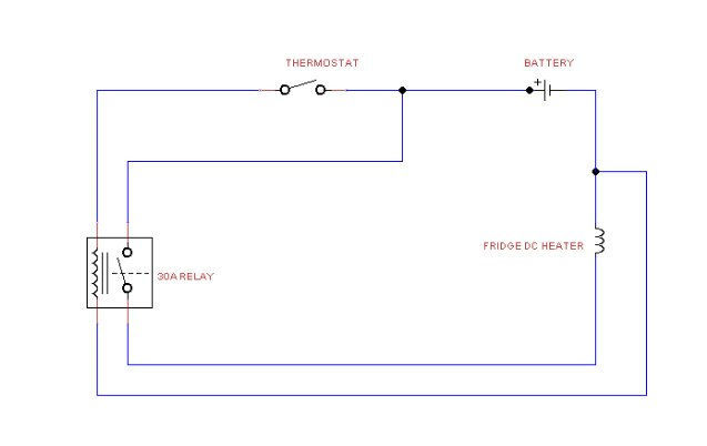
Chestcold do not fit a 12 volt thermostat to their fridges . My idea is to get a thermostat from an old freezer or fridge and put it into a Chestcold fridge . Remove the thermostat carefully from the freezer or fridge . Hang the bulb into the fridge , connect the thermostat to one wire of the 12 volt supply . Thermostats are only a switch operated by temperature . This could be a good saving of power to any body with solar panels and batteries . Has any body tried this ???
 
In theory, it's doable........in practice, not so much.

The switching contacts in a fridge/freezer thermostat are designed to switch around 1-2 Amps at 240V AC. There is a larger inrush current when the contacts first mate, but that's another story. The bulk of damage/wear incurred by contacts occurs when the current is broken (contacts open).

Your Chescold draws around 10 Amps from a 12V source....two problems....one, 10A is a hell of a lot more current than 1-2 Amps, and....even worse, you are switching DC and not AC. Switching high DC currents is a real bummer, which is why most small DC absorption fridges, like the Dometic range, don't even try it.

To successfully switch large DC currents (and have your contacts live to tell the story) requires a special magnetic arc extinguishing arrangement.

You can do it, and it will work (for a while)...but you'd better have a big box full of replacement thermostats handy :)

The only other option is a thermostat with solid-state switching......or you could try using the thermostat to operate a 12V relay with DC-rated contacts....make sure the relay is a plug-in type, 'cause you'll need to replace it too, but not as frequently.
 
I'd doubt that any on/off thermostatic switching arrangement will work, given the slow, heat-driven, non-mechanical process used in an absorption-type fridge. The thermal lag would be of the order of hours, both rising and falling, rather than the instantaneous pumping of a compressor.

An alternative approach might be to investigate varying the power level provided to the heating element, but I don't think that would be doable without incurring significant energy wastage via a rheostat.

On the gas setting, some variation is possible by simply turning down the gas flame, but the range is quite limited because even on high, the flame isn't much more than a pilot light.
 
grubstake said:
I'd doubt that any on/off thermostatic switching arrangement will work, given the slow, heat-driven, non-mechanical process used in an absorption-type fridge. The thermal lag would be of the order of hours, both rising and falling, rather than the instantaneous pumping of a compressor.

Most absorption fridges have a thermostat controlling the 240V heater element.......they don't have a thermostat controlling the DC heater element for the reasons outlined above.

From the Chescold manual:

1607769780_chescold_thermostat.jpg
 
My old Engel has a thermostat adjusted by the control knob (on/off also). What adjusts it is the variable potentiometer of the switch, altering the resistance in the circuit.

However, given it is wired to the power supply, the fridge drawing 3.0 amps when cold and running as well as resistors on the circuit board the switch is soldered to, there's no guarantee the pot uses 12 volts to operate or capable of taking a 10 amp current.

Also it is designed to work in conjunction with the compressor, evaporator and condenser specific to the fridge. So again no guarantee that even if it doesn't fail that it will give any or the correct range adjustment.

So using a thermostat from a different device is likely to fail.

Last - in most 3 way fridges i.e my vans Thetford, the adjustment knob works to alter the fridge temp on 240 VAC and LPG. The 12 volt circuit only, if working properly, maintains the temperature whilst driving and is not controlled by the thermostat. I found that my power supply which distributes 12 VDC power to the van also trickle charges the van battery as well as running the fridge. I measured the voltage at the fridge terminals when engine and fridge on at 11.9 V and it always, after 5-6 hours of driving, failed to keep the fridge at sensible temp.

I changed the wiring to remove the power supply as I have solar to charge the house battery and connected the fridge only to the car and re measured at 12.9 V and it now holds temp much better. So voltage does make a difference as assuming the current the car provides is the same, the increase in volts increases the watts to the element.
 
Jaycar sells a 12 volt D.C . relay kit that will switch 30 amps for $7. 14 . You need to solder the kit together but does not look to be much .

The thermal lag will be the same for 240 volt and 12 volt . They are both heating elements .
 
condor22 said:
I found that my power supply which distributes 12 VDC power to the van also trickle charges the van battery as well as running the fridge. I measured the voltage at the fridge terminals when engine and fridge on at 11.9 V and it always, after 5-6 hours of driving, failed to keep the fridge at sensible temp.

I changed the wiring to remove the power supply as I have solar to charge the house battery and connected the fridge only to the car and re measured at 12.9 V and it now holds temp much better. So voltage does make a difference as assuming the current the car provides is the same, the increase in volts increases the watts to the element.

Condor, Had the exact same problem with the van fridge warming after long drive. The dealer I bought the van from did the ute wiring with one of the plug wires dedicated to charging van batteries.
Overcame this problem by running a heavy wire from the ute auxiliary battery to the van batteries. No more problems.
Auxiliary battery - fuse - anderson plug - anderson plug - fuse - Van batteries.
 
Here's a circuit using a 30A relay and a thermostat:

1607856646_fridge_thermostat.jpg


A word of caution about your idea to "...hang the bulb into the fridge..."

Some fridge thermostats are air-sensing, and some are evaporator-sensing.....depending on which type you end up with will determine whether you can just hang the bulb in the fridge, or need to attach it firmly to the evaporator assembly.

After your relay has done a bit of work switching 10A DC, the contacts will end up looking like this:

1607857235_burnt_contacts.jpg


How long this takes will depend on the number of switching operations, which in turn is dependent on set temperature, ambient temperature, and internal heat load, and hours of use.

When the contacts start looking like the above, you will start losing voltage to the fridge and subsequently cooling capability.

It will pay to keep an eye on the voltage across the fridge coil from time to time.
 
Katabatic said:
Here's a circuit using a 30A relay and a thermostat:

https://www.prospectingaustralia.com/forum/img/member-images/19153/1607856646_fridge_thermostat.jpg

A word of caution about your idea to "...hang the bulb into the fridge..."

Some fridge thermostats are air-sensing, and some are evaporator-sensing.....depending on which type you end up with will determine whether you can just hang the bulb in the fridge, or need to attach it firmly to the evaporator assembly.

After your relay has done a bit of work switching 10A DC, the contacts will end up looking like this:

https://www.prospectingaustralia.com/forum/img/member-images/19153/1607857235_burnt_contacts.jpg

How long this takes will depend on the number of switching operations, which in turn is dependent on set temperature, ambient temperature, and internal heat load, and hours of use.

When the contacts start looking like the above, you will start losing voltage to the fridge and subsequently cooling capability.

It will pay to keep an eye on the voltage across the fridge coil from time to time.

Fitting a CR circuit across the relay contacts can improve longevity of the contact... being lazy, I just copied the below from the Worlds Wider Web :D :D :D

With both AC and DC, contact arcing can be minimized with the addition of a "snubber" circuit (a capacitor and resistor wired in series) in parallel with the contact, like this:

A sudden rise in voltage across the switch contact caused by the contact opening will be tempered by the capacitor's charging action (the capacitor opposing the increase in voltage by drawing current). The resistor limits the amount of current that the capacitor will discharge through the contact when it closes again. If the resistor were not there, the capacitor might actually make the arcing during contact closure worse than the arcing during contact opening without a capacitor! While this addition to the circuit helps mitigate contact arcing, it is not without disadvantage: a prime consideration is the possibility of a failed (shorted) capacitor/resistor combination providing a path for electrons to flow through the circuit at all times, even when the contact is open and current is not desired. The risk of this failure, and the severity of the resulting consequences must be considered against the increased contact wear (and inevitable contact failure) without the snubber circuit.
 
One thing many people don't realise with switchgear;

Although an AC switch, circuit breaker etc will work as a switch, they are not built to handle the arcing as depicted in the above picture.

i.e A 240 VAC 10 amp switch will handle 2400 Watts of power. If used on a 12 VDC 10 amp circuit it only handles 120 Watts and most people will say "hey only 5% of the load", but it will likely fail on DC well before it would on 240 VAC.

A good example; where many caravan manufacturers fail are the light switches. My caravans light switch wall plates for the main roof light, some downlights and the external light are 240 VAC switch plates. The van is 6 years old and used for about 4 months a year = total use of 2 years. I recently had to replace the external/lounge downlight switch as the lights were flickering, Compare this to my house where most of the switch gear is 50+ years old and still going strong. As this occurred during a trip, the constant flickering also burned out some of the LED chips in the lights and I had to replace 4 of them as well.

The same logic applies to relays, solenoids, thermostats or any other mechanical switch.

Which is why I switch my solar panels with NoArc "cushioned" circuit breakers.

Unless you have no choice don't mix AC and DC switchgear. :)
 
Thanks for all the useful replies .

The Jaycar D.C. relay switch kit I was looking at was Cat .No. KC 5434 . Out of stock on line .....
 
Yes, I agree . Had a look at some on E-bay , they also have sockets with wires hanging out. If they are rated at 40 amps , they should last a longer time at 10 amps .
 
Much better to do your own circuit with a mosfet, but I really don't think you would gain much from the whole experiment, otherwise the makers would be doing it already.

I think if you got it operating the way you want the duty cycle would be close to 100% most of the time.

In a cooler climate it would be more practical perhaps.
 
I like that temperature controller on E-bay thanks for the link . Saves the hassle of getting one out of an old fridge/freezer .

It all depends were you are , I have been in the bush near Cloncurry in winter time and have seen ice .I regret not taking a photo , next time ! So , the duty cycle would be a lot less than 100% . Most of us go prospecting in winter time .

I think it is worth a bit of experimenting , if you have a solar system and plan on living in the bush for a few months. A Chestcold could be come a good second freezer if you are out for a long time .

I have put it on my list of projects , I have sold one Chestcold fridge but still have two !
 
Before you go and spend a lot of money on parts, why not do some simple tests.

Get a probe thermometer that is on a lead, they are cheap as hell.

Set your fridge going and just manually turn it off for 30 min and back on for 30 min, then start lengthening the times etc and see if the temp holds.

Clearly you will need a lot of time for this, but it will give you a rough idea of the duty cycle required to hold temp.

Just an idea.
 

Latest posts

Top