Diy Variable voltage setup

Prospecting Australia

Help Support Prospecting Australia:

This site may earn a commission from merchant affiliate links, including eBay, Amazon, and others.
Joined
Jun 6, 2016
Messages
103
Reaction score
23
Has anyone come up with a descent variable battery setup that I can make so I can adjust my input voltage from 5.9v-8.4v for my F1A4 level 3 detector.
I'm pretty handy with a soldering iron and electronics. Just need some guidance in what is best to use. Hope someone can help.
Cheers
Firey10_0
 
Dammit, just re-read your post, I was assuming 12v battery. the below will only be applicable if battery volts are higher than regulated voltage. if you need to step up the voltage and still be adjustable then you may be able to find something suitable on fleabay already made up.

you could just use an adjustable regulator and build your own. LM317 should be suitable, ensure rated to suit current requirements and dont exceed voltage input output differential
select resistors to provide required o/p voltage, using a potentiometer turns it into an adjustable regulator.
May require heatsink if high current, work it out from data sheet
using a linear regulator will reduce battery life marginally
 
Hi bicter
Would this be stable and quiet enough to run on a metal detector without affecting it's performance. Just wondering if something so simple is good enough to do the job properly. The items that you see forsale just look to be more complex. Let me know what you or anyone else thinks.
Cheers
Firey10_0
 
Firey10_0 said:
Hi bicter
Would this be stable and quiet enough to run on a metal detector without affecting it's performance. Just wondering if something so simple is good enough to do the job properly. The items that you see forsale just look to be more complex. Let me know what you or anyone else thinks.
Cheers
Firey10_0

The best way to determine if it's going to be suitable(in the absence of full specifications) is to build it and see if there are any issues.

Assuming you are using a 12V battery, noise the linear voltage regulator would introduce will be negligible.
If you are looking for an ultra low noise regulator, there are designs on the web but you could be building a rod for your own back as they are more complex.
Step up regulators, for instance if you had a 5V battery, are by their nature noisy and should be avoided if possible,
Can you let me know what the requirements are, ie:
Input Voltage:
Output Voltage: Fixed or Variable
Output Voltage range:
Current requirement at O/P voltage:
http://www.ti.com/lit/an/snoa402b/snoa402b.pdf is the application note for the LM117/317 voltage regulator
 
Hi again
The supply voltage is only about 8.5v Max and required voltage would be from 5.9v 0.5a to 8.4v 1.5a and would need the voltage settings of atleast 5.9v, 7.2v and 8.4v.
Hope this makes sense.
Thanks
Firey10_0
 
hmm the LM317 wont do your job as it has a 3v I/O differential. therefore the absolute maximum regulated O/P would be 5.5V.

Have a look at the MIC29302BT available here https://au.rs-online.com/web/p/low-dropout-voltage-regulators/9101395/ It should meet your requirements with a bit further investigation.
Data sheet available here https://docs-apac.rs-online.com/webdocs/1385/0900766b813853ad.pdf
Have a good read of the application information starting at page 19 to see if it can be adapted to meet your needs

The Dropout Voltage for MIC29300 VOUT = 1% (6) IOUT = 1.5A Typical 250mV

(6) Dropout voltage is defined as the input-to-output differential when the output voltage drops to 99% of its normal value with VOUT + 1V applied to VIN.

Footnote: I should have asked, are the voltages you require preset or fully adjustable across the range of O/P voltages? If switch selectable voltages are required, then using a pre-selected switched resistor for each voltage may be a better solution than a potentiometer
 
Hi bicter
The voltage can be switch set at 5.9v, 7.0v and 8.4v. would be OK if it's easier as a normal potentiometer could easily be knocked to a different voltage which wouldn't be ideal.
The regulator itself looks OK. If it's not to hard could you draw up a rough circuit diagram showing how to put it together. I understand if it's too difficult but if you can thE would be great. Thanks
Firey10_0
 
I'd also be adding a crowbar circuit just for added protection and piece of mind.
 
Mr Magoo said:
I'd also be adding a crowbar circuit just for added protection and piece of mind.
I agree, particularly given the fact that I have no idea of the usage it's being put to.
Nightjars previous comment on letting the smoke out is a good reminder of the risk of deviating from the manufacturers design.

With regard to the design, I was giving Firey ideas on how they solve their problem noting they had said "pretty handy with a soldering iron and electronics". I have no intention of providing a full design as that would then potentially make me liable for any damage caused.
 
Firey10_0 said:
Hi bicter
The voltage can be switch set at 5.9v, 7.0v and 8.4v. would be OK if it's easier as a normal potentiometer could easily be knocked to a different voltage which wouldn't be ideal.
The regulator itself looks OK. If it's not to hard could you draw up a rough circuit diagram showing how to put it together. I understand if it's too difficult but if you can thE would be great. Thanks
Firey10_0

Firey,
Please refer to my reply to Mr Magoo's post.
All the information you require is available in the application information linked previously.
A rough calculation shows that for 8.4V O/P, R/R2 should be around 1K/200R to ensure the required 7ma load current while for 5.9V, R1/R2 should be 750R/200R - This needs to be confirmed by testing. Value for 7.0V can also be calculated. I couldn't see anything in the data sheet regarding suitability or associated risk of switching resistors on the adj pin. There is a possibility that switching between the voltages could introduce a spike on the supply.

The design needs to consider the change in input voltage as the battery discharges. This will be determined by the battery chemistry and given the 8.4 I/P & 8.4V O/P required, it would be very easy for the regulator to drop out of regulation. Given the 1.5A current required at 8.4V this is a real possibility.

Battery protection will be required to prevent over discharge

Any circuit design you come up with would need to be thoroughly tested before connecting to the detector.
 
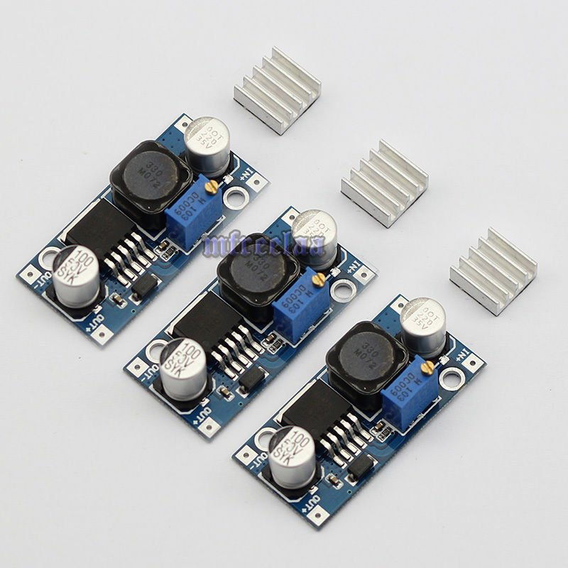
Easiest way (and cheap) is just to buy a dc - dc converter module, remove the pot on the board and replace it with an external one. Using a meter add resistors to the pot so that the range of the pot corresponds to the voltage range required.

I would probably also add a decent electro cap on the output of the module.

something like this : https://www.ebay.com.au/itm/3x-DC-D...=item417dacf661:g:yqIAAOxy3HJTGu20:rk:27:pf:0

1549489651_s-l1600.jpg
 
steelPHASE said:
Easiest way (and cheap) is just to buy a dc - dc converter module, remove the pot on the board and replace it with an external one. Using a meter add resistors to the pot so that the range of the pot corresponds to the voltage range required.

I would probably also add a decent electro cap on the output of the module.

something like this : https://www.ebay.com.au/itm/3x-DC-D...=item417dacf661:g:yqIAAOxy3HJTGu20:rk:27:pf:0

https://www.prospectingaustralia.com/forum/img/member-images/13488/1549489651_s-l1600.jpg

Thanks Pat,
They certainly are cheap enough and appear to meet Fireys requirements with a few additional external components.
I mentioned SMPS early in the piece but avoided them as as they can be inherently noisy whereas the linear isn't so much. Having said that, its been a few years since I looked at them :) It may need an inductive filter on the O/P in addition to the cap.

The OP was looking for switch selectable voltages, do you know if fitting switched resistors would work? Are there any switching spikes associated with turn on?

For info, just found a report, inc schematic, on the module here https://www.matts-electronics.com/wp-content/uploads/2018/06/XTE-SY-8.pdf
 
bicter said:
Thanks Pat,
They certainly are cheap enough and appear to meet Fireys requirements with a few additional external components.
I mentioned SMPS early in the piece but avoided them as as they can be inherently noisy whereas the linear isn't so much. Having said that, its been a few years since I looked at them :) It may need an inductive filter on the O/P in addition to the cap.

The OP was looking for switch selectable voltages, do you know if fitting switched resistors would work? Are there any switching spikes associated with turn on?

For info, just found a report, inc schematic, on the module here https://www.matts-electronics.com/wp-content/uploads/2018/06/XTE-SY-8.pdf

Yes I would also add a coil in the output as well. They aren't too noisy but I would err on the side of over engineering in this situation.

As for switching - I haven't tested that. It would probably need some damping resistor across the switches so that it never goes open circuit as it switches between values. If there is a large cap on the output, it would probably absorb most spike issues.

Turn on spikes are not something I have noticed in experimental circuits but I haven't really looked for them. Again a large cap would probably damp issues.

Note: There are different versions of these modules. Some step up, some step down. Choose what is needed but the methodology needed in this application will be the same.
- step down version : https://www.ebay.com.au/itm/5-PCS-D...wn-Power-Supply-Module-LM2596-GL/283108308772
 
Hi steel pat
Would one like this which is what Mr.Magoo posted earlier be OK. If so what is the idea of adding a transformer to the output? Could you provide me with a link to the type I would need.
https://rover.ebay.com/rover/0/0/0?mpre=https://www.ebay.com.au/ulk/itm/163427370430

I have one of these lipo battery packs and just want to regulate the voltage to the other voltages to get my f1 running smoother with different coils and grounds. Plus I'm hoping I will get better Detectoring time from a lighter battery setup.
Hope you can help me out.
Thanks
Firey 10_0
 
Firey10_0 said:
Has anyone come up with a descent variable battery setup that I can make so I can adjust my input voltage from 5.9v-8.4v for my F1A4 level 3 detector.
I'm pretty handy with a soldering iron and electronics. Just need some guidance in what is best to use. Hope someone can help.
Cheers
Firey10_0
You can use any DC-DC converter to get the Voltage high enough so later can cut it down with a Voltage regulator, like everyone here suggests LM317. I would personally use LDO regulator so to save some loss of power, which with LM317 it's not so insignificant.
 
Firey10_0 said:
Hi steel pat
Would one like this which is what Mr.Magoo posted earlier be OK. If so what is the idea of adding a transformer to the output? Could you provide me with a link to the type I would need.
https://rover.ebay.com/rover/0/0/0?mpre=https://www.ebay.com.au/ulk/itm/163427370430

I have one of these lipo battery packs and just want to regulate the voltage to the other voltages to get my f1 running smoother with different coils and grounds. Plus I'm hoping I will get better Detectoring time from a lighter battery setup.
Hope you can help me out.
Thanks
Firey 10_0

That battery pack would be ok but the wires look very thin. You will get voltage drop on higher currents. Also assuming the output is 8.4V - you will get loses in any regulator circuit so your maximum output voltage after the regulator will be less than 8.4v. If you want 8.4v as the maximum voltage to the detector, you may need to look at a higher voltage battery pack.

You don't want to use a transformer on the output. DC-DC converters basically work using high frequency switching. This can cause as slight electrical noise on the output of the converter. In most applications its not a huge deal but to eliminate any possible issues, adding an inductor in series with the output can reduce this noise significantly.

Connect battery pack to the DC - DC converter module then just add a big cap across the output of the module(i.e. 4700uf - 10000uf ) and an inductor in series with the positive rail. You could use either a toroidal or ferrite core. The value isn't super critical in this situation as long as the current rating is met. But if you decide to get all pedantic on values etc, there is heaps of info on-line to calculate correct values of inductance. Just look at the operating frequency of the DC-DC converter you choose, note the current you require and go from there. Personally I wouldn't bother. Get something like a toroidal inductor rated at 3A - 5A and you should be fine. You could even raid one out of an old SMPS (old computer p/s, old LCD/Plasma tv p/s etc)- they generally have one in the output voltage rails.
 
Hi steel pat
Some great info and ideas about the voltage regulators.
Just to clarify if I use a DC-DC buck unit then add the toroidal inductor to the output voltage to reduce any noise that I get on the output voltage. Is that correct. I haven't used these before. If u could draw me a simple sketch of a circuit that would be great.
Let me know
Cheers
Firey,10_0
 
Hey Firey,
Handy with a soldering iron.... does that mean you can design and build your own small circuits?

If so then SP suggestion is not a bad one , but i would add a couple of caps and an inductor to smooth out the output to avoid noise (these do put out noise)
on the other hand , something like an lm317 is low noise already so you may get away with a single cap on the output.
 

Latest posts

Top