Aux battery charging from 12V cig socket

Prospecting Australia

Help Support Prospecting Australia:

This site may earn a commission from merchant affiliate links, including eBay, Amazon, and others.
Condor again thanks and had noted both occasions a long run had just been done so alternator would have certainly topped battery. Speaking of which will test that also as have a wife that no matter how many times I explain keeps switching one fridge on to low mode which doesn't cut off to 10.5 Volt .................. not doing the battery any favors. Will find prob ............... completely pulled down system last night and refitted even re soldering all connections in case of a dry joint as they say time will tell. I have another 100 watt panel here I will swap out also just for the exercise to eliminate panel fault as problem as you have suggested.
Is it best to use temp compensation if available ? The Projecta instruction states to remove if not using it?
Thanks again

Baz ................... yes tech agreed with me that panel fault would most likely result in low or no voltage not over voltage.
Auto elec au sell both brands and I only asked regards failure on the off chance that I was chasing a problem that was common to the unit I had. Like most elec faults it's just a matter of tracking it down ........the fix is usually the easy part :D Yes may look at the same panels as Condor has but is charging battery ok is just this solar input over charge error it has started throwing .............. good price is always fine but at the cost of reliability becomes a fast second ;)
Will let you know what I find as to what the problem was / is :/
 
I'll be interested to see the result.

FYI The panels I use are not Ebay specials, nor from a known brand supplier, they are from a S.A. RV specialist, who is an electrical/electronics engineer that specialises in remote mobile power solutions for caravans, campers and motor homes. He sourced the cells from the U.S. and has the panels made to his specs. I believe in Malaysia, however the U.S. cell manufacturer took nearly 3 years of negotiation before he was allowed to use them.

Just in case some don't read my other threads, the cells are designed to generate not only from visible light (what most panels operate on) but also in the IR and UV spectrums. There are a couple of old sayings about "Red sky at night......" and "Red sky in the morning......" this is where the IR occurs. And, as we all know (or should know) even on a cloudy overcast day the UV index can still cause sunburn and therefore with these cells generate power.

The ones fitted to my caravan are manufactured on a plastic backing (not sure what type) about 3mm thick, they weigh 2-3kg each (bugger all when compared to rigid frame panels). They are bonded to the caravan roof with Mastick, the leading edge has 2 small screws that are fixed into the roof using blind waterproof rivnuts (security against wind at speed). The cables are also Mastik fixed to the roof (I think there is one P clip to secure a curve in the cable).

When I had the job done, I had him install the panels and feed 3+ metres of cable through the roof. I then later installed the 2 soft start 10A circuit breakers (1 for each panel), the solar controller, fuses and then connected into my van system.

To supply and fit the panels as above and supply only the CCTBKRs and controller was between $1,500 and $1,600, so not cheap.

However, I have quality gear that even in the dead of winter will charge what I use without need for mains or generator. Using my diesel heater, TV lights, pump etc averages at about 35-40AH per day.

My main motivator - I hate warm beer :)

Footnote: Although now retired, I was an electro/mechanical designer
 
Condor ........................ yes had an idea you had some sort of back ground as you have and hence directing the questions to you. ;) Appreciate the sharing of knowledge and will certainly let you know what I find regards cause of my issue. So far so good today and the sun is fair blazing where I am and actually time recording voltage put out by panel thru out the day. I have a sneaky suspicion the bad connection may have been the guilty party. But I did a few hundred K's of severe corrugations last Sunday so leaving options open here.
2 - 3 Kg is certainly a far cry from my 7.5 panel :rolleyes:
My main motivator being that I'm not a drinker is I like to eat steak ........................ even after two weeks out in 40+ heat :D
 
Bogger,

The voltage is an indicator only, i.e. 13-14v in lieu of 20+v for fault finding.

The critical thing with solar panels is the AH. What I mean here is this;

The simple math of a panel is i.e. 120W panel should put out close to 10A (watts divided by volts), however, most mono panels @120W have a rated output of about 6.7A. This is actually the wrong calculation that I've seen many use.

The key is that the unregulated voltage at max output at the panel is about 17-18v and this is what the wattage is divided by, not 12v. This voltage is what is at the solar controller input and is then regulated by the controller to the appropriate stage voltage at the regulator output.

Assuming the battery needs a charge in the Boost stage, then the output of the controller is only governed by the wattage the panel outputs. So on a poor light day, with lower output you don't get as bigger charge.

The other thing users should be aware of is, and I'll give an example; equipment - 1 x 100W panel and a 10A solar regulator. The panel may output a maximum of 6.7A so, just because you have a 10A regulator, doesn't mean you are charging at 10A. In fact due to efficiency loss the max charge will be less than 6.7A and as the regulator moves into the Absorption stage, the charging amperage will gradually reduce. This is where most of the charging time can occur.

This is why I use a battery monitor, that measures AH in and AH out to give current state of charge. The voltage will be what ever it is at that state of charge and is only of interest if it is vastly different to what is expected. That generally indicates the battery is on the fritz.
 
Condor what monitor do you run ? Many to choose from and no doub't many are probably pure rubbish also ?
:(
 
Condor just another question if you could ? Are most monitors compatible with the controllers ? Ie won't trick controller in any way as for example if you leave a solar volt reg before the controller can and will ? In saying that have noted that all earths for components etc must run via the shunt or body earth and not be connected directly to aux batt earth. Obviously if they were the monitor couldn't see them or the load one would presume?
:) Also do you run your monitor full time as have seen many are wired up to operate only once vehicle is started ?
No more probs so far with faulting and on reading more it does state on controller to connect the Aux battery to controller before connecting the solar panels to the controller, so I can only presume the make and break of the input / connection to Aux battery is what may well have tripped the solar panel input over voltage fault at this stage. ;)
 
Finally got back to this little project after a few weeks wandering around old goldfields up in Qld.

I picked up a Projecta IDC25 DC-DC charger on sale while I was up there so ready to start the install. I'm going to run some 8B&S twin cable from the starter battery into the rear cargo area via a 50A fuse and terminate that with an Andersen plug. On the outside of the portable battery box I have mounted another Andersen plug connected to the 100AH deep cycle gel battery terminals via a 50A fuse. So that's both ends of the system taken care of, but here's where I think I may have run into an issue....

I want to be able to remove the battery box and DC charger when I'm not using it, so preferably don't want to run any permanent ground wires to the chassis if I can avoid it. The DC charger has a single "common ground wire" and I was thinking I could hook that up to both the starter battery negative terminal (via the Andersen plug in the cargo area) and the aux battery negative terminal (via the battery box Andersen plug).

Any obvious flaws in this plan? From what I can work out the vehicle (2007 Forester X) doesn't have a smart alternator or any sort of voltage sensor between the starter battery negative terminal and the chassis ground, which I assume would normally be the reason for grounding the other connections....
 
Bogger, I use one of these in my caravan and another in the 4x4. The monitor is on my Galaxy mobile as an App (free download)

http://teambmpro.com/au/battery-check.html

As you may know, a voltmeter is across both the + and - terminals and in parallel to any circuit. An ammeter (or monitor) is in series with the actual circuit. Many require a shunt to dissipate the power and for you to drill holes for a qauge and therefore run wires. The BM Pro needs none of this. It will handle 100amps peak, or 80amps continuous.

The device has one hole (clearance) which you use to lock it to the battery negative terminal. The other end of the device has a threaded hole, replicating the battery terminal thread, to which you fasten all negative wires i.e. from your charger-solar controller for input and all of your output negative leads as well as chassis/main battery earth. So no holes to drill, no wires to run. It communicates to your phone via Bluetooth, but only when you open the app on your phone. It also has a battery temperature fly lead that connects to the + terminal for temp and to power the Bluetooth, which is <10mA.

I can stand outside the caravan or the 4x4 to check the batteries without having to go into battery boxes or under van seats. Because I have 2 batteries monitored and the App handles one at a time, I just chose which I want to check.

How you wire your solar controller or anything else is not a problem, providing all negative wires in or out go to the BM Pro, and that is what you do anyway without the monitor.

Obviously with engine running it will show charging voltages and input amps, but first thing in the morning before you start the engine you can monitor the auxiliary battery V, what is being used in AH and the % of charge left in the battery, which indicates what you are using between charges (overnight). I don't monitor the start battery as all my auxiliary system is IGN isolated from the MAIN via a 70A continuous run solenoid which is itself IGN switched.
 
Bundy,

1. Re the input 50A fuse - place it as near to the start battery as possible. Also consider using a self reset circuit breaker instead of a fuse and run a twin cable to the rear one for + and one for - that way chassis earth which with all the plastic and sealers used in vehicles today is a better connection. The Anderson in the back end is fine for disconnect, get one of the rubber weather covers for the Anderson to prevent accidental shorting.

2. Re connection - Anderson on the input cable from the main battery, then Anderson on the input of the IDC25, then Anderson the output of the IDC25 and finally Anderson a lead to the AGM. Using twin core cable the whole way and Anderson plugs, everything is removable.

Don't forget that by connecting directly to the main battery you are relying on any low voltage settings within the IDC25 to protect the main battery from being discharged to low. Even though I have a Redarc BCDC that can do this, I use a 70A solenoid under the hood to positively isolate the main when engine off.
 
Thanks Condor, that sounds pretty much like what I was planning to do. Just one question though - given that I have to split the common ground cable out of the IDC25 to the input and output Andersen plugs, what is the best way to splice the two cables from the plugs to the single output cable?

I was thinking I might use 3 crimp on ring terminals and bolt them together, then cover the whole lot in heatshrink......
 
Condor again thanks heaps for your info and will certainly look at your type monitor :)
Bundy myself if I want good connection I solder joints and cover with heat shrink . Usually bare a small section of main wire and splice other wire on then solder joint. Good hot iron so you can watch solder sweat thru wiring confirming a good connection otherwise you can get a dry joint which will give a bad connection. ;)
I do a lot of ECU type connections where even a small voltage drop can effect trigger voltages :)

Condor just checked your unit and looks damn good ................... and a good acceptable price also ................... ;)

Actually it looked that good I just brought one :) :) :) and might add great people to deal with ................. very helpful ;)
 
bundyjd said:
Thanks Condor, that sounds pretty much like what I was planning to do. Just one question though - given that I have to split the common ground cable out of the IDC25 to the input and output Andersen plugs, what is the best way to splice the two cables from the plugs to the single output cable?

I was thinking I might use 3 crimp on ring terminals and bolt them together, then cover the whole lot in heatshrink......

Here are some options

https://www.jaycar.com.au/multi-connect-battery-terminal-red/p/HM3089

https://www.jaycar.com.au/single-m10-power-distribution-post/p/SZ2090 I've used these before and as it is a - earth insulation isn't necessary

https://www.jaycar.com.au/butt-connector-yellow-pk-100-butt-connector-yellow-pk-100/p/PT4728 You can get these in staggered end sizes i.e. 2 wires twisted at one end into the larger end and 1 wire in the smaller end out.

The considerations are; How well can you solder, how well can you crimp, is the connection big enough to carry the load et etc.

For me, I would chose the single terminal post, its neater and well able to carry these amperages. It also means that the ring terminal crimped or soldered can be separated if needs be. Your suggestion of a screw is just as good and similar in context.

There are standards for earth post fastenings, but here's my simple build - Take the screw, place on a flat washer, then the 3 ring terminals, then another flat washer, then a spring washer then a nut. I prefer Nylock, that way it's not going to come loose.
 
Bogger said:
Condor again thanks heaps for your info and will certainly look at your type monitor :)
Bundy myself if I want good connection I solder joints and cover with heat shrink . Usually bare a small section of main wire and splice other wire on then solder joint. Good hot iron so you can watch solder sweat thru wiring confirming a good connection otherwise you can get a dry joint which will give a bad connection. ;)
I do a lot of ECU type connections where even a small voltage drop can effect trigger voltages :)

Condor just checked your unit and looks damn good ................... and a good acceptable price also ................... ;)

Actually it looked that good I just brought one :) :) :) and might add great people to deal with ................. very helpful ;)

Can't go wrong.

As I've told others many times, knowing the voltage is a "very" rough guide to battery "State of Charge" (SOC). The SOC of a deep cycle battery is measured in AH, so having a simple Ammeter in a circuit will give the immediate load, but won't record the overall v time.
The next step is to put an Ammeter on the input side of a circuit and another on the output, that will give the net effect of charge or discharge, but again not over time.

The final step is to have ammeters on input and output that calculates over time what goes in and what goes out and the net effect on SOC. That is the only accurate way of knowing what you have. i.e. The BMPRO or similar.

Again keep in mind that if you are using an AGM all day every day, keep the Depth of Discharge (DOD) to about 25% of battery capacity and if only used on the occasional trip, no more than 50% DOD. Or somewhere in between dependent on frequency of use. Using this as a guide, if you are using more than this you have 1 of 2 choices - 1. reduce the load. 2. get a bigger battery :)
 
condor22 said:
Here are some options

https://www.jaycar.com.au/multi-connect-battery-terminal-red/p/HM3089

https://www.jaycar.com.au/single-m10-power-distribution-post/p/SZ2090 I've used these before and as it is a - earth insulation isn't necessary

https://www.jaycar.com.au/butt-connector-yellow-pk-100-butt-connector-yellow-pk-100/p/PT4728 You can get these in staggered end sizes i.e. 2 wires twisted at one end into the larger end and 1 wire in the smaller end out.

The considerations are; How well can you solder, how well can you crimp, is the connection big enough to carry the load et etc.

For me, I would chose the single terminal post, its neater and well able to carry these amperages. It also means that the ring terminal crimped or soldered can be separated if needs be. Your suggestion of a screw is just as good and similar in context.

There are standards for earth post fastenings, but here's my simple build - Take the screw, place on a flat washer, then the 3 ring terminals, then another flat washer, then a spring washer then a nut. I prefer Nylock, that way it's not going to come loose.

Thanks again, I've got a decent sized hex crimp tool so I'll crimp on some ring terminals and bolt them together. Not a fan of soldering cable that big, probably more a reflection on my soldering skills/tools. I'm yet to have a properly crimped connection fail.
 
Okay ..................... after speaking with BMPRO had to cancel purchase as it won't do my set up as start battery will be seen as part of battery bank and the helpful lady informed me this unit is not suitable for a start system battery. She did inform me that in about a month they will have a unit that will be suitable for my application. BMPRO very helpful and refunded money paid without hesitation and in a happy manner.

On the solar side have found the problem to be a faulty panel :mad: 21+ volts open circuit but the minute any load placed on panel it dropped to 4.5 volts. As a result the Projecta just kept cycling in and out of alarm mode. Swapped out panel and all good. Now all I need to do is finish the battle with panel seller as it's only 6 months old. I think it's as I thought the corrugated road I was on last weekend literally shook it to death to the point it has probably internally hemorrhaged somewhere. It was one of those roads that the ladies needed to wear a sports bra :p it was that bad.
Again Condor thanks for the help and also info.
 
That's a good result from them :)

mmm, When my solenoid is connected when driving it provides power to the Redarc charger which in turn charges my auxiliary. So in effect all is connected in a manner of speaking.

But, the BMPRO is fitted to my AGM Aux only not to the start battery. Although the - negative earth is the same, the + line is through the Redarc and not connected directly to the aux.

Therefore the BMPRO is only measuring input/output at the AGM.

If an aux battery is in parallel with the start battery and charged via the alternator, a BMPRO will see it as a bank as the + and - negative lines are linked. But would only measure the loads for the items connected to the negative end of the PRO.

I personally prefer to keep the batteries totally independent particularly with AGM auxiliaries as the charging requirements don't suit alternators and I wouldn't put one under the hood. Fortunately my 4x4 doesn't have space for an under bonnet anyway :)
 
Condor yes follow that ................... one 4B is a wagon and Aux battery is in the back and my other is a ute and Aux is in tub so good there also as I don't believe AGM's like the heat from the engine bay. Makes the cost interesting when setting up two vehicles :| but one's a mountain goat truck the other is more a heavy load hauler ...................... well loads heavier than the average passenger car would legally pull.
Just waiting on a call from BMPRO techs to see if there is a way around this as the units great.
Just had a call from BMPRO and Condor again your a champ ................ they have confirmed will work just not monitor front as you said .................... so brought it .....again plus another :)

Kudos again to BMPRO as credit where it's due ....................... great service and back up.
 
Bogger said:
Condor yes follow that ................... one 4B is a wagon and Aux battery is in the back and my other is a ute and Aux is in tub so good there also as I don't believe AGM's like the heat from the engine bay. Makes the cost interesting when setting up two vehicles :| but one's a mountain goat truck the other is more a heavy load hauler ...................... well loads heavier than the average passenger car would legally pull.
Just waiting on a call from BMPRO techs to see if there is a way around this as the units great.
Just had a call from BMPRO and Condor again your a champ ................ they have confirmed will work just not monitor front as you said .................... so brought it .....again plus another :)

Kudos again to BMPRO as credit where it's due ....................... great service and back up.

Bogger, I had a feeling it would work, it's always difficult to advise when not knowing all of the details, i.e a wiring diagram or explanation of how a system is set up.
But I'm happy that you finally got it sorted.
 
I recently swapped out my 4x4 and have yet to properly install my Aux in the ne one. Knowing it would take a while, I have a temporary setup as I want to build a false floor/storage drawer for the rear end.

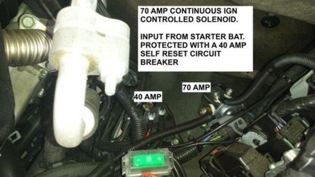
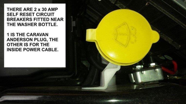
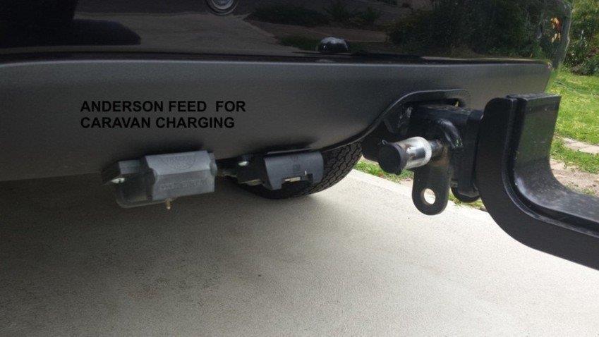
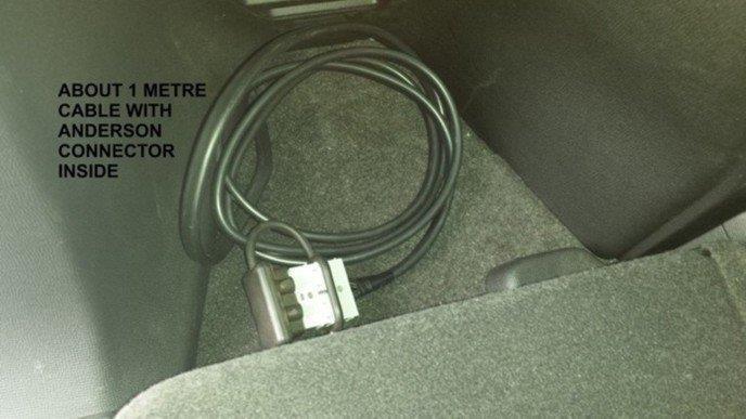
When I had the autolec. install my electric brake system, I also needed to get an Anderson plug installed for the caravan hitch (fridge power). So I had him install a 70 continuous solenoid under the hood. It is IGN controlled so disconnects when engine OFF. So with forward planning in mind, I had one twin 6mm run to the Anderson plug next to the tow hitch socket on the rear bumper and another twin 6mm run to the inside rear quarter corner of the back end.

I had him give me a bit over a metre of cable which, when I got it home, I fitted another Anderson plug.
1484187003_pic1.jpg

1484187003_pic2.jpg

1484187003_pic3.jpg

1484187003_pic4.jpg

1484187003_pic5.jpg


A picture is worth a 1000 words :)

Note the CCTBKRs and the rubber cover on the internal Anderson, more to follow.........
 
Yes running much the same set up on mine with Anderson plug out to rear but running a 150 amp plug so can power winch on car trailer from it if need be. Also hooks to camper with it's own battery. Naturally the starter cable I used is overkill for that :D but certainly doesn't get any voltage drop to camper ;)
Running same circuit breakers but use the marine one's as salt water from Fraser just destroys the metal one's ............ literally eats them.

I also cover all my plugs and enclose them to keep all the crud out. As you can see by the stone damage and sand blasting on drawbar it see's some rough country and a lot of it :eek:

1484187627_p1120002.jpg
 

Latest posts

Top